

Your gearbox
operation and maintenance expert1. About Wind Gearboxes
The gearbox is an essential part of a wind turbine, as it transfers the energy harvested by the rotor blades to the generator and enables it to rotate at a certain speed. Driven by the market demand, megawatt-size wind gearboxes have gained ground. Housed in a compact nacelle on the top of the tower, the gearbox is subjected to alternating loads, and is hard to repair if damaged. Therefore, wind gearboxes are generally required to have a design life of 20 years and extremely high reliability. Due to limitations in design, manufacturing and processing technology, assembly process, and testing techniques, among others, wind gearboxes are prone to damage, bearing wear, shaft fractures, and other problems.
In recent years, gearbox vibration has been high on the agenda, and it begins to bear in on industry professionals that vibration analysis has some economic value as it can reveal the device status. As a common headache in the machinery industry, vibration can compromise the precision and service life of a device and may also cause major safety accidents, resulting in incalculable losses. Installed in a small nacelle and subjected to alternating loads all year round, wind gearboxes suffer from severe vibration. Therefore, adequate vibration monitoring and analysis are critical for accident prevention and equipment safety improvement.
2. Analysis of Gearbox Vibration
The main reason for gearbox vibration is gear-tooth deformation that may be caused by a variety of factors, including the meshing load, assembly errors, uneven load distribution, and gear failure.
Table 1 Wind gearbox component failure rates
Component | Failure Rate (%) | Faults |
Gear | 60 | Tooth break, pitting, spalling, gluing, wear, and fatigue crack |
Bearing | 19 | Burning, inner and outer ring wear, galvanic corrosion, and retainer deformation |
Shaft | 10 | Fracture, wear, bending, and misalignment |
Casing | 7 | Deformation and cracking |
Fastener | 3 | Fracture and interference wear |
Oil seal | 1 | Wear |
The table above lists almost all the faults that may occur in a gearbox. In particular, the failure rate of gears is up to 60%. To address the gearbox vibration, we must figure out the mechanism first.
2.1 Gear Pair Dynamics

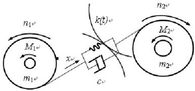
Figure 1 Gear pair dynamic model
There are stiffness changes, elastic deformation and damping in the meshing process. Based on the meshing mechanism, we create a gear pair dynamic model shown in the following equation:

Where,
x is the relative displacement of gear along the tooth contact surface under the contact stress;
m is the equivalent mass of the gear pair, ;
c is the mesh damping factor;
k(t) is the time-varying mesh stiffness;
 is the average elastic deformation caused by load;
 is the relative displacement between two gears caused by transmission errors or gear faults;
 is the vibration displacement index, reflecting the elastic force;
 is the vibration velocity index, reflecting the damping force;
 is the vibration acceleration index, reflecting the inertial force.
There are two sources of vibratory excitation:  is mesh excitation, causing vector vibration in the fault-free state;
  is caused by the internal and external excitation of the gear system, leading to fault vibration, and its characteristics depend on the fault condition. In short, gear vibration analysis is a process of identifying and locating
  .
.
2.2 Influence of Gear Specifications on Vibration
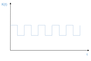
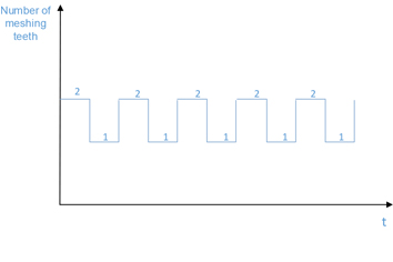
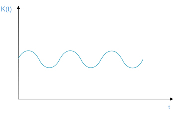
Gears can be broadly divided into straight gears and helical gears, and how they mesh and vibrate is subject to gear specifications. Figures 2 and 4 show the time-varying mesh stiffness of straight gears and helical gears, respectively. It can be seen that helical gears mesh more smoothly and therefore run more quietly. Figures 2 and 3 show how the stiffness changes with the number of meshing teeth. It can be seen that the stiffness is smaller when there is one meshing tooth than when there are two meshing teeth. When designing a gearbox, we must involve as many teeth as possible in meshing. The more the meshing teeth, the higher the contact ratio, which will lead to greater mesh stiffness and lower vibration.

Figure 2 Change in mesh stiffness of straight gears

Figure 3 Change in the number of meshing teeth of straight gears

Figure 4 Change in mesh stiffness of helical gears
Although helical gears run more smoothly, the design of helical gearboxes must take into account the influence of axial load on gear meshing, and they should differ from straight gearboxes in the axial positioning of the shaft system and bearing selection.
3. Conclusion
To analyze wind gearbox vibration, the first step is to find the source of vibratory excitation. Apart from gear meshing, which is the principal source of excitation, we should also pay attention to how other components of a wind turbine contribute to gearbox vibration. We can mitigate vibration only if we find the source of vibration.